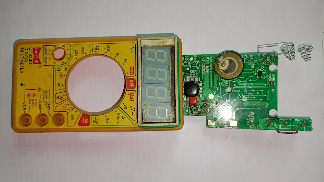
How do I exchange LCD display with 7-segment LED display
Hi Guys,
It is really amazing to visualisation instead of LCD Display ,So you can modify to your old digital multimeter into seven sigment LED Display. Let's start.
This is my personal opinion you can skip this message.
So friends, many a times our multimeter's LCD display segment gets broken, doesn't work properly and it happened to many people. Although we want to repair it, we are unable to do it as the LCD display of the multimeter is not available in the market. So today we will use seven segment LED display to solve that problem.
You can do it only if there is a problem with the LCD display, but not that. You can if you want
DT830D DIGITAL MULTIMETER
Notes for circuit diagram:-
This Circuit diagram designed according to DT830D Digital multimeter.
We don't know if the circuit layout is compatible with any other multimeter because this Circuit created according to DT830D .
But you can design any other multimeter or different brands.But in that case you have to observe the multimeter you want to modify.
First you need to observe the display output pin of Multimeter (like T0,T1,T3,T...... as per circuit diagram)
Next you find out which segments of the display are connected to the output pins of the circuit.
Then you make a drawing which pin is connected to which segment and then you make a circuit diagram of it like we have made.
Required part's
Common cathode Seven segment LED Display -4no
Single Strand Hookup Wire for PCB soldering (Connection of display to PCB)
Veroboard (For soldering the four displays)
Required part's image:-
 |
| Common cathode Seven segment LED Display -4no |
 |
| Single Strand Hookup Wire for PCB soldering (Connection of display to PCB) |
 |
| Veroboard (For soldering the four displays) |
Here the connection of a segment is shown, in this way each segment has to be connected.And for HV(red led), LOW BATTERY(yellow led), these segments can use 3mm LED or 5mm LED for indication.
Project image:-
 |
| DT830D DIGITAL MULTIMETER PCB |
CIRCUIT DIAGRAM:-
Thank you.


Post a Comment